Capacitors in Series Calculator
This capacitors in series calculator helps you evaluate the equivalent value of capacitance of up to 10 individual capacitors. In the text, you'll find how adding capacitors in series works, what the difference between capacitors in series and in parallel is, and how it corresponds to the combination of resistors.
If you want to familiarize yourself with these phenomena' formulas (and physics!), check the example – you can work out capacitors in series voltage and charge.
Do you have a circuit with capacitors arranged in parallel? Head out to Omni's parallel capacitor calculator!
Adding capacitors in series
A capacitor is an electronic component storing electric charge (or electrical energy). Capacitors can be arranged in a circuit, both in series and parallel, depending on their future application. When combined in series, the charge, Q, in each capacitor is the same. Why?
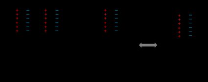
Imagine a setup composed of capacitors in series but without any source of voltage. The simplest way to visualize this situation is by using parallel plate capacitors, but it also works for cylindrical and spherical ones. In our case, each of the elements stores no charge. We then apply a voltage at the ends of the circuit.

Look at the first capacitor – as electrons move to the power source, one part of the capacitor becomes positively charged. In equilibrium, this value is +Q. The fundamental property of a capacitor is that the absolute value of the charge stored on both plates is the same but of opposite signs. As a result, the second end of this element has a charge of -Q. Next, we can't produce this charge out of a void, so it must come from the second capacitor, and that's why it also stores a charge of +Q on the adjacent end. We can continue this reasoning over and over until we reach the last element. Here, the charge doesn't come from the neighboring capacitor but the voltage source instead.
You can think about this problem as it was a black box. The charge leaves the power source from one end, goes through the box, and comes back from the other side. The overall charge has to be conserved, so the input and output values must be equivalent.
On the other hand, the voltage of capacitors in series, V, is the sum of voltages over each one separately (V₁, V₂, …). Rearranging the general formula for capacitance, we obtain the expression for the voltage over the whole circuit:

V = Q / C,
as well as for each one individually:
V₁ = Q / C₁, V₂ = Q / C₂, etc.
Once again, adding capacitors in series means summing up voltages, so:
V = V₁ + V₂ + … → Q / C = Q / C₁ + Q / C₂ + ….
We can divide each side by Q, and then we get the final form of the capacitance formula (or its inverse, precisely speaking):
1 / C = 1 / C₁ + 1 / C₂ + ….
In other words, the inverse of total capacity is the sum of the inverses of every single capacitance.
The 555 IC, in its astable mode, uses two capacitors in series to define its characteristic operation times. If you need a timer in your circuit, try our 555 timer calculator.
How to use capacitors in series calculator
Let's take a look at a computational example. What is the total capacity of four capacitors in series, where the capacitance for each one is C₁ = 2 mF, C₂ = 5 µF, C₃ = 6 µF, C₄ = 200 nF?
🔎 You can quickly decode the capacitance of any capacitor using our capacitor calculator.
-
Convert the units so that they are all the same. We can use scientific notation to make things simpler. By putting everything in terms of F, we get: C₁ = 2×10⁻³ F, C₂ = 5×10⁻⁶ F, C₃ = 6×10⁻⁶ F, C₄ = 2×10⁻⁷ F.
-
Add the inverses of capacitance:
1/C = 1 / (2×10⁻³ F) + 1 / (5×10⁻⁶ F) + 1 / (6×10⁻⁶ F) + 1 / (2×10⁻⁷ F) = 5.367×10⁶ 1/F.
-
Evaluate the inverse of this sum:
C = 1 / (5.367×10⁶ 1/F) = 1.863×10⁻⁷ F.
-
We can write the final result for adding capacitors in series using the appropriate prefix: C = 186.3 nF.
Note that this outcome may be less precise than the one from the capacitors in series calculator because we don't use as many significant figures here.
If you look closer, you will notice that the resulting capacitance is lower than any of the individual values for capacitors in series.
Capacitors in series and in parallel
As we've already found out, the arrangement of capacitors in series results in capacitance of a lower value. As you may expect, combining capacitors in parallel increases the value. We can also see some similarities between different types of electric elements:
- The formula for capacitors in series is equivalent to the equation for parallel resistors.
- The formula for capacitors in parallel is equivalent to the equation for resistors in series.
RC circuits consist of a combination of resistors and capacitors. Sometimes, there is more than one of each element, but it's usually possible to turn each of them into a single component. If we arrange the capacitors in parallel, you'll know how to estimate the outcome!
Some voltage dividers are built of capacitors in series. Check out our voltage divider calculator to find some of their benefits over standard resistive dividers!