Impedance Matching Calculator
This is the impedance matching calculator - a great tool that helps you solve problems with matching electronic elements within a circuit. In the article, you can find a short explanation of the concept of impedance matching and learn three basic impedance matching topologies (L-match, Pi-match, and T-match).
The meaning of impedance matching
The impedance matching is a common concept in electronics that helps design a circuit that maximizes the power transfer and/or minimizes signal reflection from the load.
In general, we have a source of the signal (radio transmitter, generator), and we want to transmit that signal to a load (antenna, speaker, or just a transmission line). Each of them has a characteristic impedance - a complex quantity that describes the opposition to the current flow, both static (resistance, denoted as R) and dynamic (reactance, denoted as X).
🔎 Check Omni's resistor color code calculator to learn how to read resistance in seconds!
We can ensure the maximal power transfer if the load impedance is equal to the source impedance's complex conjugate. For only resistive components, it means that the source's resistance should be equivalent to the load's resistance. In practice, we usually deal with circuits with specific reactance components, so we need a tool that tells us how to arrange electric elements.
So, how do you match an impedance or solve a circuit? In short - you need to find a capacitance and an inductance (sometimes a few of them) so that the condition for the maximal power transfer is valid. The exact values depend on the topology of the system and the current type.
Although there are many possible ways to match impedance in a system, we provide three basic circuit topologies in our impedance matching calculator, namely L-match, Pi-match, and T-match.
Three basic impedance matching topologies
To obtain a result, you should enter the following quantities:
-
The values of resistances (RS, RL) and reactances (XS, XL) of the source and the load;
-
The frequency (F) of the signal; and
-
The possibility/suppression to pass direct current. The configuration that passes DC is lowpass, and the corresponding one is a highpass match.
Sometimes you'll also need to input the quality factor (Q).
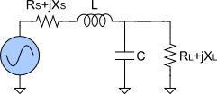
L-match circuit


The first of the systems is the L-match circuit. The name comes from the fact that two elements, an inductor, and a capacitor, align in the letter L. If you've ever heard about voltage dividers, the configuration may look familiar. If not - we recommend trying our voltage divider calculator!
As a result, you get the values of the inductance (L), the capacitance (C), and the output Q factor.
Pi-match circuit


The next circuit is Pi-match, as the three components in the middle resemble the Greek capital letter Π.
-
For the lowpass system, you receive the values of the inductance (L), source capacitance (CS), and load capacitance (CL).
-
For the highpass system, you receive the values of the capacitance (C), source inductance (LS), and load inductance (LL).
T-match circuit


The last of the configurations is T-match. At this point, you shouldn't be surprised that matching elements form a letter T, should you?
-
For the lowpass system, you receive the values of the capacitance (C), source inductance (LS), and load inductance (LL).
-
For the highpass system, you receive the values of the inductance (L), source capacitance (CS), and load capacitance (CL).
How to use this impedance matching calculator?
Our tool is pretty straightforward to use. You only need to type input parameters, and you'll get the results immediately. Take a look at an example:
-
Choose the type of your circuit. Let it be
Pi-Match. -
Set the frequency to
110 MHz. -
Enter source resistance and capacitance, which are
50 Ωand0 Ω, respectively. -
Repeat the same for load inputs -
150 Ωfor the resistance and0 Ωfor the reactance. -
Type input Q factor as
2.5. -
Disable passing DC (
Block DC Currentoption).
And that's all! Your outcome values should be:
-
18.95 pFfor the capacitance. -
60.78 nHfor the source inductance. -
86.81 nHfor the load inductance.
🔎 If in need, you can decode the capacitance of any capacitor with our capacitor calculator.