Thin-Film Optical Coating Calculator
This thin-film optical coating calculator will calculate the reflectivity and interference type of light reflected by a thin optical film. We can evaluate the optical path difference and reflectivity by using Fresnel equations, Snell's law of refraction, and trigonometry. Then we can discern the type of interference. Alternatively, we can determine the minimum anti-reflection coating thickness required for a particular wavelength of light.
In this article, we will learn more about thin-film interference, optical path difference, and how to calculate reflectivity.
Thin-film interference and optical path difference
When light hits the interface between two different mediums, a portion of it is reflected back into the first medium, while the remaining light is transmitted through to the second medium. Depending on the material, some light could be absorbed. The transmitted light undergoes refraction if there is a difference in the refractive indices. You can determine the refractive index of your medium with our index of refraction calculator.
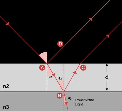
If we place a thin-film between these two mediums, something interesting happens – the top and the bottom interfaces will reflect light into the first medium, resulting in interference of light waves. Learn more about the dual nature of light with our De Broglie wavelength calculator.

In order to assess the type of interference, we need to calculate the optical path difference, which describes the phase shift the two different light waves undergo by virtue of their different optical path length. It is given by:
where:
- – Optical path difference between the two reflected light waves;
- – Refractive index of the thin-film;
- – Thickness of the thin-film; and
- – Refraction angle in the thin-film.
Furthermore, if the refractive index of the first medium is less than the second medium, then there will be a or radian phase change in the reflected light.
The reflected light waves can interfere in the following ways:
- Constructive interference: When the reflected light waves' crests and troughs overlap each other and increase the resultant wave amplitude.
- Destructive interference: When the reflected light wave's crests overlap with troughs, destroying the resultant wave amplitude.
- Intermediate: Overlapping state, resulting in a wave with amplitude somewhere between the maximum and minimum values.
Based on the OPD and phase change, the conditions for different interference types are given in the following table:
Phase shift | At top and bottom interfaces | At top or bottom interface |
|---|---|---|
Refractive indices | ||
OPD for constructive interference | ||
OPD for destructive interference |
where:
- – Refractive index of the first medium;
- – Refractive index of the thin-film;
- – Refractive index of the final medium or substrate;
- – Any positive integer; and
- – Light's wavelength.
Note that if , there is no phase shift in the reflected light at both the top and bottom interfaces.
How to calculate minimum anti-reflective coating thickness
Anti-reflective coating is a thin optical coating over a transparent material (say, glass) used to reduce reflection. We can reduce reflection by ensuring that the reflected light waves interfere destructively and eliminate each other. Multiple layers of such coating are often employed each targeting specific light wavelengths.
The following equations and inequalities summarize the conditions for destructive interference in such a coating:
This leads to the following minimum anti-reflective coating thickness:
How to calculate reflectivity
Reflectance, reflectivity, or power reflection coefficient, refers to the fraction of incident light reflected at the interface. Fresnel equations for s-polarized and p-polarized reflectivity for non-magnetic media are given by:
where:
- – s-polarized reflectivity;
- – Angle of incidence;
- – Angle of transmittance or angle of refraction; and
- – p-polarized reflectivity.
Similarly, transmissivity is a measure of light transmitted at the interface. It is given by:
where:
- – s-polarized transmissivity; and
- – p-polarized transmissivity.
But how do you calculate reflectivity in our case, where you have three mediums involved? One way to do so would be:
- Evaluate the reflectivity at the first interface, and .
- Calculate the reflectivity at the second interface, and .
- Evaluate the transmissivity of this reflected light at the first interface, and (the indices '21' represent transmissivity from the second medium to the first).
- Calculate the actual fraction of light reflected from the second interface to the first medium as and .
- Finally, obtain overall reflectivity as and .
🔎 A special case of these Fresnel equations yields Brewster's angle. It is the angle at which all reflected light is of one particular polarisation while the refracted/transmitted light is of the other polarization. Learn more about Brewster's angle with our brewster angle calculator.
How to use this thin-film optical coating calculator
This thin-film optical coating calculator has a lot going on under its hood, but it is relatively straightforward to use:
- Enter the incident angle and the optical film thickness, along with refractive indices of the three mediums involved. The calculator will calculate reflectivity, optical path difference, and interference type.
- Enter the film's wavelength and refractive index, and this thin-film optical coating calculator will evaluate the minimum thickness of the anti-reflective coating.