Boost Converter Calculator
Omni Calculator's boost converter calculator is here to help you find the duty cycle and inductance of your circuit, characterizing your boost converter.
Keep with us in this article to explore:
- What is a boost converter?
- How to make a boost converter?
- How do you choose the boost converter switching frequency?
- What is the difference between a boost converter and an inverter?
- What is the difference between a buck and a boost converter?
- How do you calculate the switch-on period for a boost converter?
So, let us step up your voltage with the boost converter calculator.
What is boost converter? How do you make a boost converter?
The boost converter is an example of a DC-to-DC converter, which steps up the input DC voltage to a higher output DC voltage. It is also a class of the so-called switched-mode power supply (SMPS), which are electronic circuits that incorporate a switching regulator to convert electrical power efficiently.
They have several applications in battery-powered devices, power supplies, LED drivers, and electric vehicles.
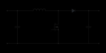
A typical boost converter can be built using key components: an inductor, switch, diode, capacitors, and a control circuit. We can see an example of a standard boost converter in the circuit diagram below.

In this diagram, and are the input and the output capacitors, is the inductor, represents the diode, is a transistor working as switch for the boost converter, and and are the input and the output voltages, respectively.
Components, duty cycle and inductance
This DC-to-DC converter can be characterized by computing the duty cycle and the inductance. The duty cycle measures how long the switch stays on relative to the total switching period. It can be determined using the formulas below:
where:
- — Maximum value of the input voltage;
- — Output voltage measured at the end of the circuit;
- — Period when the electronic switch is on; and
- — Period of the switching oscillatory cycle.
The duty cycle has a direct impact on the efficiency of the circuit. Basically, for low values of , we have high efficiency with a cost of low boost ratio . If we have high values of , then we have low efficiency due to high conduction and inductor losses. Therefore, the ideal scenario is to have moderate values of , optimizing the balance between the efficiency and the boost ratio.
You can learn more about the duty cycle by accessing our duty cycle calculator.
Another relevant parameter to characterize the boost converter is the inductance, whose equation is
where:
- — Switching frequency or the rate of the power switch in the boost converter; and
- — Maximum ripple current.
It is relevant to find a proper value for to keep the desired conduction mode and the stable operation of the boost converter.
We know that it was a lot to learn and understand. However, you do not need to be worried; our boost converter calculator is here to do all the hard work for you.
🙋 Boost your knowledge of inductance and frequency by checking our solenoid inductance calculator and our frequency calculator.
Boost converter calculator: an example
In this example, we will show how easy and intuitive using our boost converter calculator is. Thus, let us consider the following set of parameter to our DC-to-DC converter: , , , and .
By substituting them in our boost converter calculator, we can determine the respective values for the duty cycle and the inductance: and .
You should always remember that our calculator works back and forward, so you can use a given duty cycle and the inductance to determine other parameters, such as the ripple current.
As you can see, we can characterize our boost converter in the blink of an eye.
FAQs
How do you choose the boost converter switching frequency?
One important aspect when looking for the right switching frequency for your boost converter is finding the proper balance between efficiency, size, thermal performance, and EMI (electromagnetic interference). You can guide yourself by considering the following specifications:
-
For high efficiency, larger components, easier thermal and EMI management, use low frequencies (fsw = 20 - 200 kHz); and
-
For compact design, smaller components, considering more EMI and higher switching losses, prefer high frequencies (fsw = 200 kHz - 1 MHz).
What is the difference between boost converter and inverter?
The main difference between a boost converter and a boost inverter is that the first is a DC-to-DC converter, while the second is a DC-to-AC converter. They are built with different components and also have different applications. The boost converter is used in battery chargers, LED drivers, and solar panels, while the boost inverter is applied to solar systems, UPSs (uninterruptible power supplies), and industrial motors.
What is the difference between buck and boost converter?
The buck converter and boost converter are both types of DC-DC power converters; however, they have opposite purposes regarding voltage regulation. The buck converter has the objective to step down the voltage of your circuit (Vout < Vin), while the boost converter steps up the voltage (Vout > Vin). They are built with the same components. However, the inductor is placed in the output path of the buck converter.
How do you calculate switch-on period for a boost converter?
Let us consider a duty cycle D = 50% and a switching frequency fsw = 100 kHz. You can determine the switch-on period by following the steps below:
-
Write the duty cycle as decimals: D = 0.5.
-
Use the switching frequency to find the switching period:
Tsw = 1/fsw = 10-5 s
-
Take the equation for the switch-on period:
Ton = D ⋅ Tsw = 5 × 10⁻⁶ s