Buck Converter Calculator
Omni Calculator's buck converter calculator is here to help you find the duty cycle and inductance of your electronic circuit.
Keep with us in this article to explore:
- What is a buck converter?
- How does a buck converter work?
- How do you choose the switching frequency of the buck converter?
- How to build a buck converter?
- Can a buck converter step up voltage?
- How do you calculate the switch-on period for a buck converter?
So, do not worry and step down your voltage with the buck converter calculator.
What is a buck converter? How does a buck converter work?
The buck converter is an example of a DC-to-DC converter, which steps down the voltage of a circuit. For this reason, it is also known as a step-down converter. Moreover, the buck converter is a class of the so-called switched-mode power supply (SMPS), which are electronic circuits that incorporate a switching regulator to convert electrical power efficiently. If you want to explore another example of an SMPS circuit, access our boost converter calculator.
They have several applications in battery-powered devices, solar panels, LED lighting, computer and data centers, and electric vehicles.
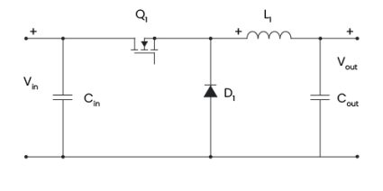
A standard buck converter consists of an inductor, switch, diode, capacitors, and a control circuit. The circuit diagram below shows an example of a standard buck converter.

In this diagram, and are the input and the output capacitors, is the inductor, represents the diode, is a transistor working as switch for the buck converter, and and are the input and the output voltages, respectively.
The buck converter circuit works by controlling the energy transfer from the input to the output through switches, an inductor, and its capacitors. The transistor and the diode are employed in the buck converter to control the current flow through the inductor. By adjusting the duty cycle of the transistor, this step-down converter efficiently reduces a higher input voltage to a lower output voltage.
Buck converter duty cycle, switching frequency and buck converter inductance
This DC-to-DC converter can be characterized by computing the duty cycle and the inductance. The buck converter duty cycle measures how long the switch stays on relative to the total switching period. It can be determined using the formulas below:
where:
- — Maximum value of the input voltage;
- — Output voltage measured at the end of the circuit;
- — Period when the electronic switch is on; and
- — Period of the switching oscillatory cycle.
The duty cycle has a direct impact on the circuit's efficiency. High values of result in low efficiency due to high conduction and inductor losses. Therefore, the ideal scenario is to have moderate values of , optimizing the balance between efficiency and thermal performance.
You can learn more about the duty cycle by accessing our duty cycle calculator.
Another relevant parameter is the buck converter inductance, whose equation is:
where:
- — Switching frequency or the rate of the power switch in the buck converter; and
- — Maximum ripple current.
If you want to remember how to convert the frequency to period, try our frequency calculator.
Moreover, it is relevant to find a proper value for for acceptable inductor and output capacitor values and to reduce the step-down converter's output voltage ripple.
We know that it was a lot to learn and understand. However, you do not need to be worried; our buck converter calculator is here to do all the hard work for you.
Buck converter calculator: an example
In this example, we will show how easy and intuitive using our buck converter calculator is. Thus, let us consider the following set of parameters to our buck converter circuit: , , , and .
By substituting them in our tool, we can determine the respective values for the buck converter duty cycle and the inductance: and .
You should always remember that our calculator works backward and forward, so you can use a given duty cycle and the inductance to determine other parameters, such as the switching frequency of the buck converter.
FAQs
How do you choose the switching frequency of the buck converter?
The switching frequency is a critical parameter of your buck converter regarding its applicability. This frequency can balance the performance, efficiency, and component size of the devices in your circuit. You can consider the following values for typical frequency ranges:
- 100 kHz to 500 kHz for low-power applications;
- 1 MHz to 3 MHz for compact components; and
- Above 3 MHz for lightweight and high-efficiency designs.
How to build a buck converter?
You can build a simple buck converter using one inductor, switch, diode, some capacitors, and a control circuit. The inductor stores and smoothens energy for steady current flow. The switch controls power transfer via duty cycle. The diode provides a current path when the switch is off. The capacitors reduce noise and ripples and stabilize the input and output voltages. The control circuit regulates the switching of the transistor and adjusts the duty cycle.
Can a buck converter step up voltage?
No, a buck converter is not able to step up voltage once it is designed to be a step-down converter. This means that it will provide an output voltage smaller than the input voltage. If you would like to step up your voltage, then you need to use a boost converter.
How do you calculate the switch-on period for a buck converter?
Let us consider a duty cycle D = 30% and a switching frequency fsw = 100 kHz. You can determine the switch-on period by following the steps below:
-
Write the duty cycle as decimals: D = 0.3.
-
Use the switching frequency to find the switching period:
Tsw = 1/fsw = 10-5 s
-
Take the equation for the switch-on period:
Ton = D ⋅ Tsw = 3 × 10⁻⁶ s