Flyback Converter Calculator
Omni Calculator flyback converter calculator is here to help you find the duty cycle, peak current, and inductance for the primary and secondary sides of your electrical circuit.
Keep with us in this article to explore:
- What is a flyback converter?
- How does a flyback converter work?
- What are the disadvantages of a flyback converter?
- What is a flyback transformer?
- How to calculate the flyback voltage?
So, you can choose freely whether to step up or down your voltage, with our flyback converter calculator.
What is a flyback converter?
A flyback converter is a buck-boost converter, which can be used to step up (boost) or step down (buck) the voltage of a given circuit. This converter makes a DC to DC conversion with galvanic isolation between the input and the output.
Galvanic isolation means a transformer is placed in the converter, providing electrical isolation between the input and output circuits. So, no direct current flows between these circuits; however, it still allows energy to be transferred between the two sides. Such a dispositive is critical in many applications for safety and noise reduction.
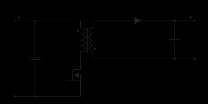
This transformer is built by a coupled inductor with a gapped core. An example of a standard flyback converter is shown in the diagram below where:
- is a switching transistor, typically a MOSFET;
- and are capacitors;
- and are the primary and secondary windings of a transformer;
- is a diode for a proper current flow;
- and are the input and the output voltages; and
- is the voltage rectified by the diode , contributing to charging the output capacitor and powering the load.

🙋 You can learn more about MOSFET, boost and buck converters by accessing our dedicated tools: MOSFET calculator, boost converter calculator, and buck converter calculator.
Flyback converter design, primary and secondary windings of a transformer, peak current and more
Now that we know the flyback converter design, we can approach the equations behind it. The key parameters that we can compute are the duty cycle, the peak current, and the inductance of the primary and secondary sides.
The duty cycle represents the fraction of one switching period during which the switching device is turned on. It determines how long energy is stored in the transformer during each switching cycle. The duty cycle can be determined using the equation below:
where:
- — Switching frequency; and
- — Time the switch is on during one switching cycle.
The duty cycle can also be found using the voltages of the circuit and the so-called windings ratio. The alternative formula to compute it in this buck-boost converter is:
where:
- — Input voltage;
- — Output voltage;
- — Voltage rectified by diode ; and
- — Windings ratio.
The equation for the windings ratio is such that:
where:
- — Number of turns in the primary winding of the coupled inductor; and
- — Number of turns in the secondary winding of the coupled inductor.
Now that we have found the duty cycle for the flyback converter design, we can use it to determine the peak currents and inductances on each side of the circuit.
The peak current and the inductance on the secondary side of the circuit are given by:
where:
- — Peak current flowing through the secondary winding of the flyback transformer;
- — Output current; and
- — Inductance on the secondary winding.
Moreover, the peak current and the inductance on the primary side of the circuit are determined using the following equations:
We know that it was a lot to learn. However, our flyback converter calculator is here to make all the hard work for you in the blink of an eye.
Flyback converter calculator: an example
In this example, we will show how easy and intuitive using our calculator is. Thus, let us consider the following set of parameters for our flyback converter:
- ;
- ;
- ;
- ;
- ; and
- .
By substituting them in our tool, we can determine the respective values for the duty cycle, the peak current, and the inductance for the primary and secondary sides of your circuit: , , , and .
You should always remember that our calculator works backward and forward. Thus, you can use the duty cycle, the peak currents, and inductances to determine other parameters, such as the switching frequency or the output current.
How does a flyback converter work?
The flyback converter transfers energy from an input source to an output circuit. It works by storing energy in a transformer's magnetic field (in the switch-on phase) and then releasing it to the output circuit (in the switch-off phase). This DC to DC conversion can be applied in chargers, adapters, control circuits, and low-power electronics.
What are the disadvantages of a flyback converter?
The main disadvantages of a flyback converter are:
- Limited power capability;
- High voltage stress;
- Low efficiency;
- High thermal losses; and
- Electromagnetic interference.
Despite these issues, the flyback converter remains popular for low-cost, low-power, and isolated applications.
What is a flyback transformer?
A flyback transformer is a coupled inductor with a gapped core, and it is a key component of a flyback converter. The transformer provides the flyback converter's galvanic isolation and is also designed to store and transfer energy between the primary and secondary sides of the circuit. This transformer is ideal for DC-to-DC conversion applications.
How do you calculate the flyback voltage?
You can determine the flyback voltage by following the steps below:
-
Take the equation for the duty cycle:
D = N ⋅ Vfb/(N ⋅ Vfb+Vin)
-
Isolate the flyback voltage Vfb:
Vfb = D ⋅ Vin/((1 - D) ⋅ N)
-
You can also find the flyback voltage using the formula:
Vfb = Vout + Vrect
where Vout and Vrect are the output voltage and the voltage on the rectifier, respectively.