Omni Calculator's inverting buck-boost converter calculator is here to help you find the duty cycle and inductance of your electronic circuit.
Keep with us in this article to explore:
- What is an inverting buck-boost converter?
- The duty cycle of an inverting buck-boost circuit and inductance.
- What is the difference between an inverting and a non-inverting buck-boost converter?
- How does a buck-boost converter work?
- What are the advantages and disadvantages of a buck-boost converter?
- What is the on-time interval of an inverting buck-boost converter?
With our inverting buck-boost converter calculator, you can choose freely whether to step up or down your voltage.
What is an inverting buck-boost converter? The inverting buck-boost design
An inverting buck-boost converter, or buck-boost converter with an inverted topology, is a class of DC-DC converters used to step up or step down a given input voltage.
The working process of a buck-boost design is similar to that of a flyback or forward converter; however, the buck-boost converter can invert the voltage polarity. Therefore, if you start with a positive input voltage in your electronic circuit, the converter will provide a negative output voltage, and vice versa.
In this calculator, we will consider the absolute values of the input and output voltages so that the voltage polarity is not determinant when calculating other parameters, such as the duty cycle and the inductance. It is relevant to point out that the buck mode and boost mode depend on the value of the duty cycle. More details about this topic will be presented in the next section.
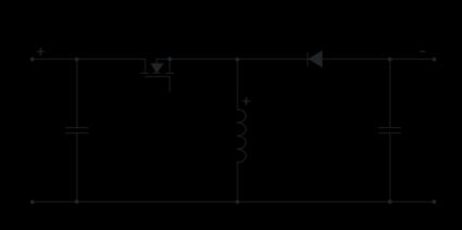
A simple configuration of an inverting buck-boost converter is shown below where:
- — Switching transistor, typically a MOSFET;
- and — Capacitors;
- — Diode for a proper current flow;
- — Inductor, allowing the output voltage to be either boosted or bucked; and
- and — Input and the output voltages.
🙋 You can learn more about flyback and forward converters by accessing our dedicated tools: flyback converter calculator and forward converter calculator.
The duty cycle of an inverting buck-boost circuit, negative output voltage, buck mode and boost mode
Now that we know the details about the inverting buck-boost design, we can approach the equations behind this converter. The key parameters that we can compute are the duty cycle and the inductance.
The duty cycle of an inverting buck-boost circuit can be computed using the following equations:
where:
- — Input voltage;
- — Output voltage;
- — On-time interval;
- — Switching frequency; and
- — Duty cycle.
The last equation can be rewritten as:
Therefore, we observe that:
- The converter is in the buck mode if , which means ; and
- The converter is in the boost mode if , which means .
Once we have found the duty cycle, we can use it to determine the inductance of . The inductance can be computed using the formula:
where:
- — Inductance; and
- — Maximum ripple current.
We know that understanding all the concepts behind this DC-DC converter is not easy. However, our inverting buck-boost converter calculator is here to do the hard work for you.
🙋 You can explore other DC-DC converters by accessing the buck converter calculator, and the boost converter calculator.
Inverting buck-boost converter calculator: an example
In this example, we will show how easy and intuitive using our calculator is. Thus, let us consider the following set of parameters for our forward converter:
- ;
- ;
- ; and
- .
By substituting them in our inverting buck-boost converter calculator, we can determine the respective values for the duty cycle and the inductance: , and .
You should always remember that our calculator works backward and forward. Thus, you can use the duty cycle and the inductance to determine other parameters, such as the switching frequency or the input voltage.
FAQs
What is the difference between an inverting and a non-inverting buck-boost converter?
The main difference between an inverting and a non-inverting buck-boost converter is the output voltage polarity. Non-inverting buck-boost converters, such as the SEPIC (single-ended primary-inductor converter) or the Ćuk converter, do not invert the polarity of the output voltage.
However, converters with an inverting buck-boost design change the voltage polarity. Both converters are versatile and widely applied, but the choice depends on whether an inverted or non-inverted output voltage is needed.
How does a buck-boost converter work?
A buck-boost converter is a member of the DC-DC converters that can step up (boost) or step down (buck) an input voltage to produce a regulated output voltage. The buck-boost design with an inverted topology allows an output voltage with inverted polarity. The operation of a buck-boost converter is based on energy storage and transfer using an inductor and switching components.
What are the advantages and disadvantages of a buck-boost converter?
The main advantages of a buck-boost converter are:
- High efficiency;
- Compact size; and
- It supports inverting output, if necessary.
The main disadvantages of a buck-boost converter are:
- It generates EMI (electromagnetic interference);
- The complex control of its duty cycle; and
- Its efficiency is lower during extreme duty cycles.
How you can find the on-time interval of an inverting buck-boost converter?
You can compute the on-time interval of an inverting buck-boost converter by following the steps below:
-
Take the switching frequency of your converter: fsw.
-
Take the value of the duty cycle: D.
-
Substitute these parameters in the equation for the on-time interval:
Ton = D/fsw